16×2 LCD and i2c LCD with Arduino Examples
Description:
16×2 LCD with Arduino– in this article, I am going to show you how to use normal and i2c LCD with Arduino in very detail.
Liquid crystal displays (LCD):
LCD (in English “Liquid Crystal Displays” -LCDs-) offer a very quick and eye-catching to show messages. We can classify them on character LCDs and graphics LCDs (GLCD). The first is used to display ASCII and are sold in different sizes (16×2, 20×4…) where the first number indicates the number of characters that fit in a row, and the second number is the number of rows that fit on the screen. The latter is used to display, in addition to text, drawings, and images, and are also marketed in different sizes, which are defined by the number of pixels they can display (128×64, 128×128…). Character LCDs, on the other hand, you can display small icons of 5×7 pixels or similar The most common character LCDs are 4-bit or 8-bit, depending on the number of wires (bits) they need to have connected to the circuit in order to receive or send data. Be careful, only wires that are strictly transferred are counted of data since in reality an LCD needs not only 4 or 8 wires to work, but several more (such as power, ground, reset …). Other features that may (or may not) have character LCDs are the ability to illuminate the background of display (ideal for low ambient light environments) or the ability to use multiple background colors (and not just white/black on blue/green, which is usually the norm), etc.
Amazon purchase links:
Super Starter kit for Beginners:
PCB small portable drill machine:
*Please Note: These are affiliate links. I may make a commission if you buy the components through these links. I would appreciate your support in this way!
16×2 LCD pins description:
Each 16×2 LCD model is different, so it is imperative to consult your specific datasheet to be able to distinguish the different connection pins offered and their general characteristics. Anyway, the most common is that a 16×2 LCD standard offer:
- 16×2 LCD power pin:
Normally, the 5 V that provides the Arduino board is already fine, but there are models that require 3.3 V, so you have to watch this) and another pin to connect the screen to Earth. It is convenient to connect a voltage divider between the power source power and display power pin to avoid possible damage. To calculate the optimal value of this resistance, you should consult two values in the LCD datasheet: the maximum current supported for the light background and the voltage drop caused by it. Making use of the Law of Ohm, if this voltage drop is subtracted from the 5 V and the result is divided between that maximum current, we will obtain the value of the resistance (rounding up) we need. For example, if the maximum current is 16mA and the voltage drop is 3.5 V, the resistance should be (5 – 3.5) / 0.016 = 93.75 ohms (or 100 ohms rounding to a value standard). If the datasheet cannot be queried, a safe value to use is 220 ohms, although such a high value will make the backlight fainter.
- 16×2 LCD contrast:
This pin must be connected to the central pin of a potentiometer of our circuit (which in turn has to have its outer pins connected to power and ground, respectively), so that by regulating the potentiometer we can adjust the contrast of the display.
- 16×2 LCD “ES”, “EN” and “RW” pins:
That each must be connected to a digital pin on the Arduino board. The “RS” pin is used for the microcontroller to tell the LCD if it wants to display characters or if you want to send control commands (such as changing the cursor position or clearing the screen for example). Specifically, if for that pin the LCD detects a LOW signal, the received data will be processed as commands to execute, and if it detects a HIGH signal, the data received will be the text to display on the screen. The “EN” pin sets the “enable” line, which serves to warn the LCD that the microcontroller is going to send data (either control or printable). This warning occurs every time the signal received by that pin changes from HIGH to LOW. Finally, the pin “RW” is used to define if you want to send data to the LCD (the most common) or receive them from her (very rare); if we are in the first case, this pin it should receive a LOW signal and in the second case it should receive a signal HIGH, so, since normally we will not need it at all, we will we will almost always connect to ground.
- Several pins (4 or 8, depending on whether the LCD is “4-bit” or “8-bit”)
that must also connect each one to a digital pin on the Arduino board. They are used to establish communication lines in parallel where they are transferred the data and the control commands from the Arduino board to the LCD. Must know that an 8-bit LCD can work perfectly with just four connected data cables (i.e. functioning as a 4-bit LCD), but it will do so at a slower speed.
- Two dedicated pins for the backlight circuit:
(one to receive the power supply and the other pin to connect to the ground). If the screen does not have backlight (also called “feedback”), these pins or not will exist or they will not be used at all.
I insist that the above list of “necessary pins” is only a “common minimum” of all the LCD models on the market. Is absolutely It is, therefore, necessary to consult the datasheet of the model that we have on hand to confirm how many pins that particular LCD consists of, what function they perform, and what location they have. There are several models, for example, that offer the possibility of changing the color of the backlight to anyone; this is possible because they have internally of three LEDs (each one of primary color –red, green, and blue–), which must be connected to the PWM output pins of the Arduino board using three more pins offered by the screen, apart from those already described. This feature it’s called RGB (for “Red-Green-Blue”). 16×2, 20 x 4, these LCDs are compatible with the “LiquidCrystal” Arduino official library.
The LiquidCrystal library:
The first thing we must do to be able to use compatible 16×2 LCD screens with the official LiquidCrystal library it is to declare a global variable of type “LiquidCrystal”, which will represent within our sketch the LCD object that we want to control.
|
1 |
LiquidCrystal lcd; |
Once the lcd object is created, the first thing we must to do is set the screen size to be able to work with it. This is done using the following function:
lcd.begin():
- specifies the dimensions (columns and rows) of the screen. It has two parameters: the first is the number of columns that the screen and the second is the number of rows. It has no return value. This function must be executed before you can start printing any character in it.
From here, we can write characters on the screen with any of the following three functions:
lcd.write():
writes a character to the screen. As the only parameter it has that character, which can be explicitly specified in quotes simple or through a variable of type “byte” (whose value can be have been obtained from a sensor, or read from the serial channel, etc.). Your data of return is of type “byte” and is equal to the number of bytes written (therefore, if everything is correct, it will be worth 1), although it is not mandatory to use it.
lcd.print():
write a piece of data (of any type) on the screen. As the first parameter has that data, which can be either a character of type “char” as a character string but can also be integer numeric (“Int”, “long”, etc.). Optionally, a second can be specified parameter that indicates, in the event that the data to be written is integer, the format with which it will be seen: it can be the predefined constant BIN (which will indicate that the number will be displayed in binary format), HEX (in hexadecimal) and DEC (in decimal, which is its default value). Your data of return is of type “byte” and is worth the number of bytes written, although it is not mandatory to use it.
lcd.createChar():
Create a fully custom character. They can create up to eight different characters of 5×8 pixels each. The appearance of each character is specified by an 8-byte array. Each one of these bytes represents a row of pixels. Each row of pixels is drawn depending on the values of the last five bits (the ones on the right) of its corresponding byte: if the bit is equal to 1, the relevant pixel will be painted and if is worth 0, no. However, this function does not write the character on the screen, so just believe it; In order to write it, we must use lcd.write(). This function has two parameters: the first is the identification of the character to create (it can be a number between 0 and 7) and the second is the array with the “Drawing” of the pixels.
lcd.clear(): clears the screen and positions the cursor in its upper corner left to write the next text from there. It has no parameters nor return value.
lcd.home(): positions the cursor in the upper left corner of the screen to write the next text from there. If you also want clear the screen, then you have to use lcd.clear(). It has neither parameters or return value.
lcd.setCursor(): positions the cursor on the specified column and row as parameters to write the next text from there. Her first parameter is the column in which you want to place the cursor (the first is the number 0) and its second parameter is the row (the first is the number 0 too). It has no return value.
lcd.cursor() – Displays the cursor as an underline line on the position where the next character will be written. It has neither parameters nor return value. There is also the lcd.noCursor() function, which hides the cursor (and it has neither parameters nor return value).
lcd.blink(): displays the blinking cursor (assuming this is visible). It has neither parameters nor return value. There is also the function
lcd.noBlink(), which prevents the cursor from blinking (and has no parameters or return value).
lcd.display(): turns on the screen (after turning it off using lcd.noDisplay()). The lcd.noDisplay() function turns off the screen but does not it loses the current text, so if you run lcd.display() it will return to restore the text (and cursor) that was previously displayed. None of the two functions has neither parameters nor return value.
lcd.scrollDisplayLeft(): scrolls screen content (text and cursor) one space to the left. It has neither parameters nor return value. There is also the lcd.scrollDisplayRight() function, which scrolls the contained one space to the right (and which has neither parameters nor return value).
lcd.autoscroll(): enables automatic content scrolling displayed on the screen. This causes each character to be “pushed” into one space for the next, in the sense marked by the functions
lcd.leftToRight() or lcdrightToLeft() The effect visual is that each new character will appear in the same position within the screen. It has no parameters or return value. There is also the lcd.noAutoscroll() function, which avoids this behavior (and does not has neither parameters nor return value).
lcd.leftToRight(): sets the writing direction of the text on the screen. By default, it is already from left to right (that is, the characters that are print they will do it in that sense), so it would not be necessary to input execute this function unless it had previously been executed
lcd.rightToLeft(): which sets the writing direction from right to left. Neither of these two functions will affect the text in any case. previously written on the screen before its execution, and they have neither parameters or return value.
16×2 LCD with Arduino Pins Descriptions:
16×2 LCD has a total of 16 pins.
Pin number1 is the Ground and will be connected with the Arduino’s Ground.
Pin number 2 is the VDD and will be connected with the Arduino’s 5 volts.
Pin number 3 the contrast pin, this pin will be connected with the potentiometer. The LCD contrast can be then controlled using a potentiometer……
Pin number 4 is the RS which stands for register select. It can be set to 0 or 1.
0 is equal to an instruction input
1 is equal to data input
Pin number 5 is the read or write pin of the 16×2 LCD. It can be set to 0 or 1.
0 means Write to an LCD module and
1 means Read from the LCD module
Most commonly we use 0, as we print text and sensors values on the LCD. For this, we simply connect this pin with the ground, as ground means 0.
Pin number 6 is the enable pin.
Pin number 7 to 14 are the data pins which are also represented by D0 TO D7. SO
Pin number 7 = D0
Pin number 8 = D1
Pin number 9 = D2
And so on up to pin number 14 which is D7
To reduce the wiring we will be using this LCD in a 4-bit configuration, so out of these 8 pins, we will be using only 4 pins D4 to D7.
Pin number 16 will be connected with Arduino’s 5 volts and finally
Pin number 16 will be connected with the Arduino’s Ground.
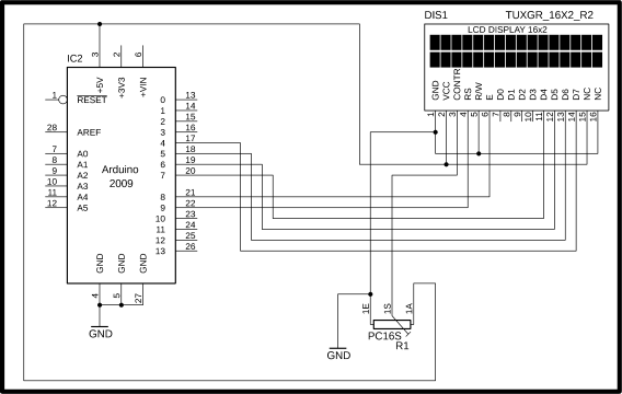
16×2 LCD with Arduino Circuit diagram:
16×2 LCD Arduino Programming Examples:
Example1: how to print smiley face on 16×2 LCD:
|
1 2 3 4 5 6 7 8 9 10 11 12 13 14 15 16 17 18 19 20 21 22 23 24 25 26 27 28 29 30 31 32 33 34 35 36 37 38 39 40 41 42 43 44 45 |
#include <LiquidCrystal.h> #define rs 9 #define en 8 #define d4 7 #define d5 6 #define d6 5 #define d7 4 // initialize the library with the numbers of the interface pins LiquidCrystal lcd(rs, en, d4, d5, d6, d7); byte smile[8] = { 0b00000, 0b00000, 0b01010, 0b00000, 0b10001, 0b01110, 0b00000, 0b00000 }; void setup() { lcd.begin(16, 2); lcd.createChar(1, smile); lcd.setCursor(0, 0); lcd.write(1);lcd.write(1);lcd.write(1); } void loop() { } |
output:

Example2: 16×2 LCD left side-scrolling text with a smiley face in Arduino:
|
1 2 3 4 5 6 7 8 9 10 11 12 13 14 15 16 17 18 19 20 21 22 23 24 25 26 27 28 29 30 31 32 33 34 35 36 37 38 39 40 41 42 43 44 45 46 47 48 49 50 51 |
#include <LiquidCrystal.h> #define rs 9 #define en 8 #define d4 7 #define d5 6 #define d6 5 #define d7 4 // initialize the library with the numbers of the interface pins LiquidCrystal lcd(rs, en, d4, d5, d6, d7); byte smile[8] = { 0b00000, 0b00000, 0b01010, 0b00000, 0b10001, 0b01110, 0b00000, 0b00000 }; void setup() { lcd.begin(16, 2); lcd.print("Fawad khan"); lcd.createChar(1, smile); lcd.setCursor(11,0); lcd.write(1); } void loop() { for (int leftSideCounter = 0; leftSideCounter < 13; leftSideCounter++) { lcd.scrollDisplayLeft(); delay(500); } } |
output:
Example3: 16×2 LCD right side scrolling text with a smiley face in Arduino:
|
1 2 3 4 5 6 7 8 9 10 11 12 13 14 15 16 17 18 19 20 21 22 23 24 25 26 27 28 29 30 31 32 33 34 35 36 37 38 39 40 41 42 43 44 45 46 47 48 49 50 51 |
#include <LiquidCrystal.h> #define rs 9 #define en 8 #define d4 7 #define d5 6 #define d6 5 #define d7 4 // initialize the library with the numbers of the interface pins LiquidCrystal lcd(rs, en, d4, d5, d6, d7); byte smile[8] = { 0b00000, 0b00000, 0b01010, 0b00000, 0b10001, 0b01110, 0b00000, 0b00000 }; void setup() { lcd.begin(16, 2); lcd.print("Fawad khan"); lcd.createChar(1, smile); lcd.setCursor(11,0); lcd.write(1); } void loop() { for (int rightSideCounter = 0; rightSideCounter < 29; rightSideCounter++) { lcd.scrollDisplayRight(); delay(500); } } |
output:
Example4: how to make progress bar animation in 16×2 LCD using Arduino:
|
1 2 3 4 5 6 7 8 9 10 11 12 13 14 15 16 17 18 19 20 21 22 23 24 25 26 27 28 29 30 31 32 33 34 35 36 37 38 39 40 41 42 |
#include <LiquidCrystal.h> #define rs 9 #define en 8 #define d4 7 #define d5 6 #define d6 5 #define d7 4 // initialize the library with the numbers of the interface pins LiquidCrystal lcd(rs, en, d4, d5, d6, d7); byte a[8] = {B00000, B00000, B00000, B00100, B00100, B00000, B00000, B00000 }; byte b[8] = {B00000, B00000, B10001, B10001, B10001, B10001, B00000, B00000 }; byte c[8] = {B11111, B10001, B10001, B10001, B10001, B10001, B10001, B11111 }; void setup() { lcd.begin(16, 2); lcd.createChar(0, a); lcd.createChar(1, b); lcd.createChar(2, c); lcd.clear(); } void loop() { int i; for (int i = 0; i < 16; i++) { lcd.setCursor(i, 0); lcd.write(byte(0)); delay(250); lcd.setCursor(i, 0); lcd.write(byte(1)); delay(250); lcd.setCursor(i, 0); lcd.write(byte(2)); delay(250); lcd.setCursor(i, 0); lcd.write(byte(1)); delay(250); lcd.setCursor(i, 0); lcd.write(byte(0)); delay(250); } delay(1000); lcd.clear(); } |
output:
Example5: how to Make a notice board using 16×2 LCD and Arduino:
|
1 2 3 4 5 6 7 8 9 10 11 12 13 14 15 16 17 18 19 20 21 22 23 24 25 26 27 28 29 30 31 32 33 34 |
#include <LiquidCrystal.h> #define rs 9 #define en 8 #define d4 7 #define d5 6 #define d6 5 #define d7 4 // initialize the library with the numbers of the interface pins LiquidCrystal lcd(rs, en, d4, d5, d6, d7); void setup() { lcd.begin(16, 2); Serial.begin(9600); } void loop() { if (Serial.available()>0) { delay(100); lcd.clear(); while (Serial.available() > 0) { lcd.write(Serial.read()); } } for (int textScorllCounter = 0; textScorllCounter < 13; textScorllCounter++) { lcd.scrollDisplayLeft(); delay(500); } } |
output:
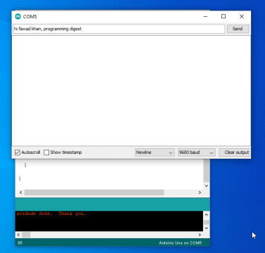
write a message in serial monitor and press enter
Example6: how to read analog sensor data on 16×2 LCD using Arduino:
Here I used the same 16×2 LCD circuit as I mentioned above, but here I just use a variable resistor as an analog sensor which is connected with an analog pin A1.
|
1 2 3 4 5 6 7 8 9 10 11 12 13 14 15 16 17 18 19 20 21 22 23 24 25 26 27 28 29 30 31 |
#include <LiquidCrystal.h> const int anySensor = A1; //connect any sonsor with Al int SensorData= 0; #define rs 9 #define en 8 #define d4 7 #define d5 6 #define d6 5 #define d7 4 // initialize the library with the numbers of the interface pins LiquidCrystal lcd(rs, en, d4, d5, d6, d7); void setup() { lcd.begin(16, 2); Serial.begin(9600); pinMode(anySensor, INPUT); } void loop() { SensorData = analogRead(anySensor); lcd.clear(); lcd.print("sensor Value:"); lcd.setCursor(0,1); lcd.print(SensorData); delay(200); } |
output:
16×2 I2C LCD:
Common 16×2 LCD displays have the drawback of requiring many wires to connect to the circuit. As a consequence, on our Arduino board we few pins may be available for use in other things. A solution to This drawback is the use of 16×2 LCD screens that use a system of communication with the Arduino board different from the one already mentioned, such as I2C protocols (which only uses the SDA and SCL lines), or serial (using only the RX and TX lines), mainly.
Actually, these 16x2LCD screens are exactly the same as we studied above, but they incorporate a small plate on the back (called “Backpack”)

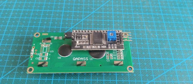
that includes a small microcontroller in charge of carrying out the translation of the appropriate protocol (I2C, Serial, etc.) to the “standard” signals that the 16×2 LCD screen understands.
16×2 I2c LCD addresses:
As you can see the driver module is also provided with A0, A1, and A2 links which can be used to set the i2c address. As you can see no links are fitted the 7-bit address is 0x27 which you have to confirm in the datasheet, maybe your 16×2 LCD have a different i2c address. The links control the least significant 3 bits, fitting the link sets the bit low.
I2C 16×2 LCD circuit diagram:
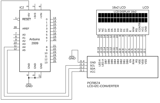
As you can see, the circuit diagram is simple. All 16-pin PCF8574 controller module are connected with the 16×2 LCD pins. With these connections, you can turn any 16 × 2 LCD display into an i2c-compatible LCD display. The 16×2 LCD VCC pin is connected with Arduino’s 5 volts, the SDA pin of the 16×2 LCD is connected with Arduino’s A4 analog pin, the SCL pin of 16×2 LCD is connected with Arduino’s A5 analog pin, while the GND pin of the LCD is connected with Arduino’s Gnd. Using only two A4 and A5 pins we can control the 16 × 2 LCD screen.


As you can see I connected the wire as per the circuit diagram. Now download the required libraries and add into your Arduino library
Required libraries for 16×2 I2c lcd:
How to add a library for i2c LCD in Arduino:
First, click on the sketch, in sketch dropdown list click on include library, when you click on include library a new dropdown list will be opened in that list simply click on add .zip library as you can see in the below figure

When you click the add .zip library a window will be opened for library selection

Select your library and simply click on the open button as you click the open button the library will be added into the Arduino library folder automatically as you can see in the below figure my wire library is added.

Repeat the same steps for the LiquidCrystal_I2C library.

I added both libraries successfully.
16×2 i2c LCD Arduino Programming Examples:
Example1: how to print a simple message on 16×2 i2c LCD using Arduino:
|
1 2 3 4 5 6 7 8 9 10 11 12 13 14 15 16 17 18 19 20 |
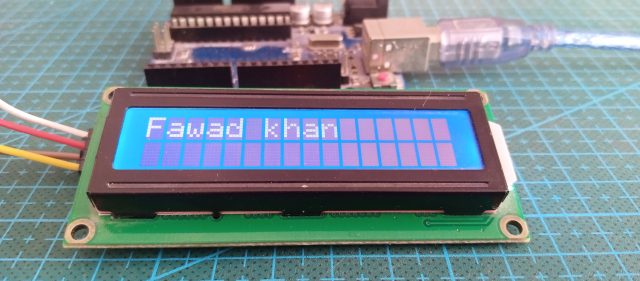
//libraries download links are given below. #include <Wire.h> #include <LiquidCrystal_I2C.h> LiquidCrystal_I2C lcd(0x27,16,2); //0x27 is the i2c address, while 16 = columns, and 2 = rows. void setup() { lcd.init(); //Init the LCD lcd.backlight(); //Activate backlight lcd.home(); } void loop() { lcd.clear(); lcd.print("Fawad khan"); delay(10000); } |
output:
Example2: how to read sensor data on 16×2 i2c LCD:
|
1 2 3 4 5 6 7 8 9 10 11 12 13 14 15 16 17 18 19 20 21 22 23 24 25 26 |
//libraries download links are given below. #include <Wire.h> #include <LiquidCrystal_I2C.h> LiquidCrystal_I2C lcd(0x27,16,2); //0x27 is the i2c address, while 16 = columns, and 2 = rows. const int anySensor = A1; //connect any sonsor with Al int SensorData= 0; void setup() { lcd.init(); //Init the LCD lcd.backlight(); //Activate backlight lcd.home(); pinMode(anySensor, INPUT); } void loop() { SensorData = analogRead(anySensor); lcd.clear(); lcd.print("sensor Value:"); lcd.setCursor(0,1); lcd.print(SensorData); delay(200); } |
output:
If you enjoyed this article, be sure to check out my other pieces for more great content!
Related Articles:
Automatic School Bell using Arduino, DS1307 and 16×2 LCD
Arduino RTC DS3231 Time and Date display on a 16×2 LCD
Arduino16x2 i2c LCD, Nodemcu 16×2 i2c LCD Code & Library
Photodiode, Phototransistor and IR Sensor with Arduino
Photoresistor | LDR Arduino based Projects
Blynk app for remote monitoring Nodemcu esp8266 and Arduino